1. Product Overview
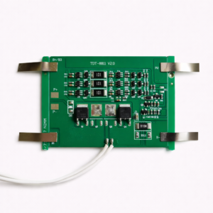
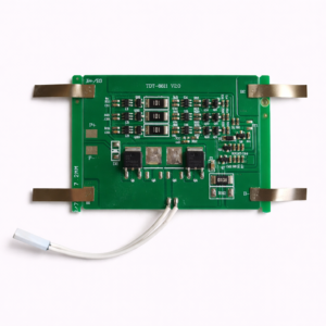
The EIK-4S-6235 is a hardware Battery Management System designed for four LiFePO4 cells connected in series. It is marked as a 4S LFP 20A BMS and is intended for compatible 12.8V nominal LiFePO4 battery packs.
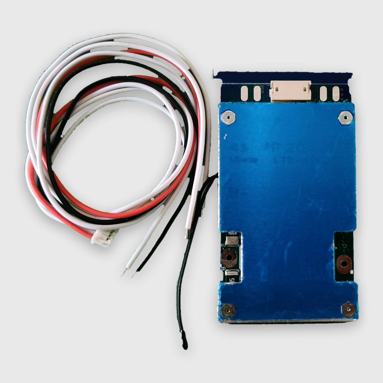
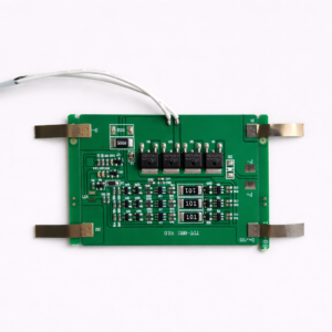
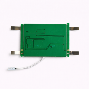
The board includes a five-wire cell-sensing harness and a visibly fitted temperature-sensor lead. Its blue protective covering shields the main power components while leaving the high-current connection points and sensing connector accessible.
The board marking shows a common negative charge and discharge connection identified as C−/P−. The exact protection thresholds, charging-current rating and balancing specifications are not stated and should not be assumed.
2. Main Technical Specifications
| Specification |
Details |
| Model |
EIK-4S-6235 |
| Product type |
Hardware Battery Management System |
| Battery chemistry |
LiFePO4 / LFP |
| Cell configuration |
4S |
| Nominal pack voltage |
12.8V |
| Typical compatible full-charge voltage |
14.6V |
| Current rating marked on board |
20A |
| Port configuration |
Common negative port |
| Battery-negative terminal |
B− |
| Charge/discharge-negative terminal |
C−/P− |
| Cell-sensing connection |
Multi-pin connector |
| Cell-sensing harness |
Five-wire harness included |
| Temperature sensor |
Sensor lead visibly fitted |
| Bluetooth or app support |
No |
| Communication interface |
Not provided |
| Balancing current |
Not specified |
| Maximum charging current |
Not specified |
| Exact protection thresholds |
Not specified |
3. Included Components
The supplied set visibly includes:
- One EIK-4S-6235 4S LFP 20A hardware BMS
- One five-wire cell-sensing harness
- Pre-fitted multi-pin connector
- Pre-fitted black temperature-sensor lead
- Metal heat-spreading/protective plate
- High-current B− and C−/P− connection points
The wire colours and sequence must be verified before connecting the harness. Do not assign cell-tap positions based only on wire colour.
4. Connection Points
B− Terminal
Connects to the negative terminal of the first cell or the main negative end of the 4S battery pack.
C−/P− Terminal
Common negative connection used for charging and discharging, according to the marking visible on the board.
Cell-Sensing Connector
Connects to the individual series-cell voltage points through the supplied five-wire harness.
The pack-positive connection normally remains common between the battery, charger and load, but installation must follow the wiring diagram applicable to this exact board.
5. Suitable Applications
This BMS may be suitable for compatible 4S LiFePO4 battery packs used in:
- 12.8V LiFePO4 battery assemblies
- Solar lighting and small solar-storage systems
- UPS and backup battery packs
- Portable power equipment
- Robotics and automation projects
- DC electronic equipment
- DIY LiFePO4 battery projects
- Replacement and battery-repair applications
The actual load and charging current must remain within the verified operating limits of the BMS and battery cells.
6. Compatibility Note
Before purchasing or installing this BMS, verify:
- Battery chemistry is LiFePO4 / LFP
- Battery configuration is exactly 4S
- Nominal pack voltage is 12.8V
- Charger is suitable for a 4S LiFePO4 battery
- Required charging current
- Required continuous and peak discharge current
- Cell-sensing connector and wire sequence
- B− and C−/P− terminal locations
- Temperature-sensor requirements
- Physical dimensions and mounting space
This BMS is not suitable for 4S NMC, lithium-ion or conventional LiPo cells with a 4.2V full-charge voltage per cell. It must also not be used with 3S, 5S or other cell configurations.
7. Installation Guidance
- Assemble and balance the four LiFePO4 cells before connecting the BMS.
- Connect the cell-sensing wires in the correct voltage sequence.
- Verify each adjacent sensing-wire voltage with a multimeter before plugging the connector into the BMS.
- Connect B− to the battery-pack negative terminal.
- Connect the charger and load negative to C−/P−.
- Use correctly sized conductors and secure high-current connections.
- Insulate all exposed terminals after installation.
- Do not allow tools, wires or metal objects to short any terminals.
- Confirm correct total pack voltage before connecting the charger or load.
8. Safety Note
- Incorrect sensing-wire order can permanently damage the BMS.
- Never connect the harness by relying only on wire colour.
- Do not reverse battery polarity.
- Do not exceed the BMS or battery-cell current rating.
- Keep the board away from water, conductive debris and loose metal objects.
- Do not use the BMS if it is damaged, burnt or unusually hot.
- Ensure the temperature sensor is positioned securely against the battery pack.
- Installation should be performed by a person familiar with LiFePO4 battery-pack wiring and safety.