

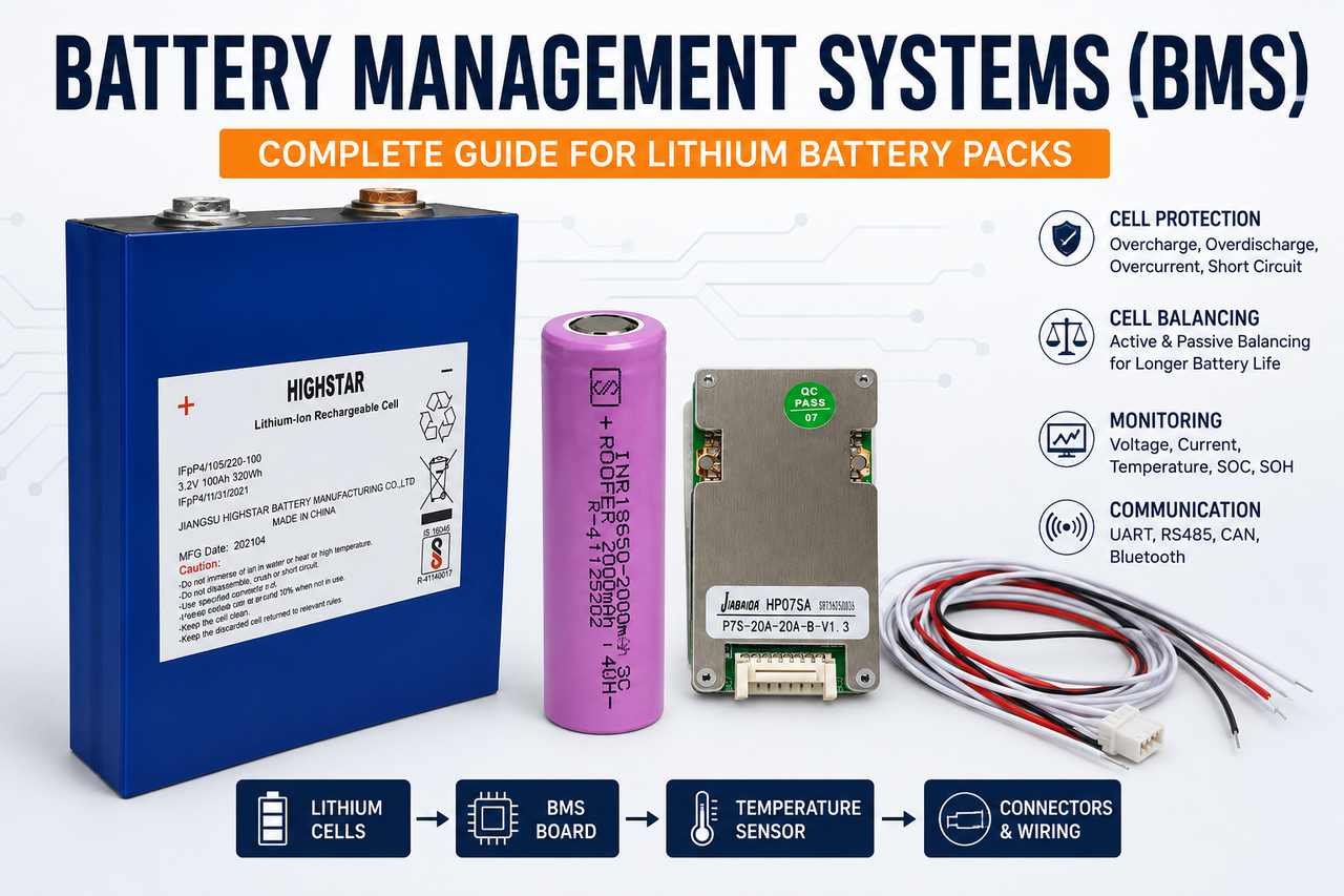
Understand BMS Protection, Cell Balancing, SOC, Communication and Selection for LiFePO₄, NMC and Lithium-Ion Batteries
A lithium battery pack may look like a simple box with positive and negative terminals, but internally it is a carefully controlled electrical system.
The cells store energy. The busbars, nickel strips and cables carry current. The charger sends energy back into the pack. The motor controller or inverter draws power from it.
The Battery Management System, commonly called the BMS, supervises all these activities.
A correctly selected BMS helps prevent the battery from being overcharged, deeply discharged, overheated or overloaded. It also monitors individual cell groups, estimates the remaining charge and may communicate with an electric vehicle, charger or solar inverter.
However, a BMS cannot work properly if it is paired with the wrong cells, an unsuitable charger or incorrectly sized wiring.
The battery cells and BMS must therefore be selected as one complete system.
This guide explains how a BMS works, what protections it provides, how cell balancing operates and how to choose the correct BMS for prismatic LiFePO₄ cells, cylindrical lithium-ion cells, NMC battery packs, electric scooters and solar energy-storage systems.
What Is a Battery Management System?
A Battery Management System is an electronic control unit that monitors and protects a rechargeable battery pack.
Depending on the design, it can measure:
- Individual cell-group voltage
- Total battery voltage
- Charging current
- Discharge current
- Battery temperature
- BMS temperature
- Remaining battery charge
- Cell imbalance
- Protection and fault conditions
When the battery moves outside the permitted operating range, the BMS can limit or stop charging and discharging.
In smaller batteries, the BMS may be a single circuit board installed inside the battery casing.
In larger electric vehicles or stationary energy-storage batteries, the BMS may include:
- Separate cell-monitoring boards
- A main control unit
- Temperature sensors
- Current sensors
- Contactors
- Pre-charge circuits
- Communication modules
- Fault logging and diagnostics
The design can vary widely, but the basic purpose remains the same:
The BMS helps keep every part of the battery operating within safe electrical and temperature limits.
Why Lithium Batteries Need a BMS
Lithium cells have strict voltage limits.
Charging a cell above its recommended upper voltage can damage the chemistry. Discharging it too far can also reduce capacity, increase internal resistance or make the cell unsafe to recharge.
This is especially important in a battery pack because many cells are connected together.
When cells are connected in series:
- Their voltages add together
- The same current flows through every series group
- The weakest group can limit the whole battery
Imagine a battery with 16 cell groups connected in series.
If 15 groups are healthy but one group has lower capacity, that weak group may reach its minimum voltage first during acceleration or heavy discharge.
The total pack voltage may still look acceptable, but the weakest cell group may already be outside its safe range.
That is why checking only the total battery voltage is not enough.
The BMS must monitor every series group separately.
Battery Cells and the BMS Must Be Selected Together
A BMS cannot be chosen without knowing which cells will be used in the battery.
The following details directly influence BMS selection:
- Cell chemistry
- Number of cells in series
- Cell capacity
- Maximum continuous current
- Peak current
- Charging current
- Battery application
- Expected temperature
- Required communication
Battery packs may use different cell formats and chemistries.
LiFePO₄ prismatic cells
Large LiFePO₄ prismatic cells are commonly used in:
- Solar batteries
- Home energy-storage systems
- E-rickshaws
- Inverter batteries
- Commercial EV batteries
- Telecom and backup power systems
Prismatic cells are available in capacities such as 50Ah, 100Ah, 200Ah, 280Ah and above.
Their large capacity makes them suitable for high-energy battery packs with fewer parallel connections.
Cylindrical lithium-ion cells
Cylindrical lithium-ion cells such as 18650, 21700 and 32700 formats are often used in:
- Electric scooters
- E-bikes
- Portable power systems
- Small EV batteries
- Custom lithium packs
- Power tools
Multiple cells are connected in parallel to achieve the required Ah capacity and current capability.
NMC lithium cells
NMC lithium cells are widely used when compact size, lower weight and high energy density are important.
They are common in:
- Electric scooters
- Electric motorcycles
- Compact EV battery packs
- Removable battery systems
- High-energy portable packs
An NMC battery requires an NMC-compatible BMS with the correct cell-voltage settings.
The Main Parts of a BMS
A typical BMS contains several important sections.
1. Cell-voltage monitoring circuit
Thin balance or sensing wires connect the BMS to each series group.
These wires allow the BMS to measure:
- Voltage of every cell group
- Highest cell voltage
- Lowest cell voltage
- Difference between the highest and lowest groups
This information is used to detect overcharge, deep discharge and imbalance.
The number of balance wires depends on the number of series groups.
For example:
- 4S battery: four series groups
- 13S battery: thirteen series groups
- 16S battery: sixteen series groups
- 20S battery: twenty series groups
- 24S battery: twenty-four series groups
The BMS must support the exact series configuration of the pack.
2. Current sensor
The BMS measures the current entering and leaving the battery.
This may be done using:
- A shunt resistor
- A Hall-effect current sensor
- A dedicated current-sensing circuit
Current measurement allows the BMS to detect:
- Charge overcurrent
- Discharge overcurrent
- Motor starting current
- Inverter surge
- Short-circuit current
- Total energy entering and leaving the pack
The same current information may also be used to estimate State of Charge.
3. Temperature sensors
Temperature sensors may be placed near:
- Cells
- Busbars
- BMS MOSFETs
- Cable terminals
- Battery casing
- Contactors
A small battery may use one or two sensors, while a large battery pack may require several.
The BMS can stop charging or discharging if the measured temperature moves outside the permitted range.
4. MOSFETs or contactors
The BMS needs a way to connect or disconnect the battery.
Small and medium battery packs often use MOSFETs.
Larger EV and energy-storage batteries may use high-current contactors.
The BMS may separately control:
- Charging
- Discharging
- Both charge and discharge paths
When the battery charge falls too low, the BMS can stop power from leaving the pack while keeping the charging path available.
5. Control processor
The processor is the decision-making section of the BMS.
It receives voltage, current and temperature data, compares those readings with programmed limits and decides whether the battery should continue operating.
The processor may also calculate:
- State of Charge
- State of Health
- Remaining energy
- Allowed charging current
- Allowed discharge current
- Fault history
- Number of cycles
6. Communication interface
A smart BMS may communicate through:
- Bluetooth
- CAN bus
- RS485
- UART
- Wi-Fi
- Proprietary communication systems
Communication allows users or connected equipment to view battery data.
A smart BMS can communicate with a mobile app, vehicle or inverter. Explore our smart BMS for lithium batteries for suitable EV and energy-storage applications.
How a BMS Monitors Individual Cell Groups
Cell voltage is one of the most important measurements inside a lithium battery.
Consider a 16S LiFePO₄ battery with these readings:
- Highest cell group: 3.45V
- Lowest cell group: 3.38V
- Voltage difference: 0.07V
A 70mV difference may indicate mild or significant imbalance depending on:
- State of Charge
- Battery age
- Current load
- Cell chemistry
- Pack capacity
- Whether the difference increases during charge or discharge
The BMS constantly compares each cell-group voltage with programmed thresholds.
If one group rises too high during charging, the BMS may stop charging even when the other groups are not yet full.
If one group falls too low during discharge, the BMS may disconnect the motor or inverter even though the complete battery still shows voltage.
This explains why some batteries shut down during acceleration but appear normal a few seconds later.
The weak group drops sharply under load, triggers protection and then recovers after the load is removed.
How Overcharge Protection Works
During charging, the voltage of every cell group rises.
The charger controls the overall pack voltage, while the BMS checks each group individually.
A typical sequence is:
- The charger supplies current to the battery.
- One cell group may reach its maximum permitted voltage before the remaining groups do.
- The BMS begins balancing if balancing conditions are met.
- If the voltage continues rising, the BMS stops charging.
- Charging may resume after the cell voltage falls below the release value.
The BMS is not a replacement for the charger.
The charger must still match:
- Battery chemistry
- Maximum charging voltage
- Charging current
- Connector polarity
- Charging profile
- Communication requirements
Using a charger with the wrong voltage can repeatedly force the BMS into protection.
How Deep-Discharge Protection Works
During discharge, cell voltage gradually falls.
If one group falls below the programmed low-voltage limit, the BMS disconnects the load.
This prevents the cell from being deeply discharged.
The sequence may happen as follows:
- The battery supplies current to the scooter, e-rickshaw or inverter.
- A weaker cell group loses voltage faster.
- Heavy acceleration causes its voltage to drop sharply.
- The group crosses the BMS low-voltage limit.
- The BMS disconnects the discharge path.
- The battery voltage rises slightly after the load is removed.
This voltage recovery can make diagnosis confusing.
A battery may measure normally after the vehicle switches off, but it may still contain a weak cell group.
For this reason, battery testing should often include a controlled load test.
How Overcurrent Protection Works
Every cell and battery pack has a safe current limit.
The BMS monitors the current and disconnects the battery when the current exceeds the programmed level.
Overcurrent may be caused by:
- Rapid acceleration
- Motor stall
- Heavy cargo
- Steep hill climbing
- Inverter overload
- Incorrect controller setting
- Short circuit
- Damaged wiring
- Undersized battery
A BMS may use different current limits for different situations.
For example:
- Continuous discharge current
- Peak discharge current
- Charging current
- Short-circuit current
A BMS labelled 100A may not always support 100A continuously.
Its true capability depends on:
- MOSFET quality
- Cooling
- Heat sinking
- PCB copper thickness
- Cable size
- Ambient temperature
- Installation method
The BMS rating should therefore be chosen with a realistic safety margin.
In electric scooter applications, choosing an NMC BMS designed for the required voltage and current helps the battery handle acceleration, charging and everyday use more reliably..
How Short-Circuit Protection Works
A short circuit creates a sudden and very high current path.
The BMS detects the abnormal current rise and opens the discharge path.
Short-circuit protection normally acts faster than ordinary overcurrent protection.
However, the BMS should not be the only safety component in the battery system.
A properly designed pack may also need:
- DC fuse
- Battery breaker
- Insulated connectors
- Correct cable protection
- Contactor
- Pre-charge circuit
The fuse provides an additional layer of protection if the BMS cannot interrupt the fault safely.
How Temperature Protection Works
Battery temperature affects performance, charging and service life.
High temperatures can increase battery ageing and create safety risks.
Very low temperatures can also be harmful, especially during lithium charging.
Temperature rise may come from:
- High current
- Loose terminals
- Undersized cables
- Damaged cells
- Poor ventilation
- BMS MOSFET heating
- High ambient temperature
- Frequent fast charging
A well-designed BMS may use separate limits for:
- Charge temperature
- Discharge temperature
- Cell temperature
- BMS board temperature
Temperature sensors should be placed near likely hot spots, not only where they are easiest to install.
What Is Cell Balancing?
Cells in a series battery do not remain perfectly equal forever.
Small differences develop because of:
- Manufacturing variation
- Different temperatures
- Unequal ageing
- Internal resistance differences
- Leakage current
- Slightly different capacities
- Uneven electrical connections
Cell balancing reduces the voltage difference between groups.
There are two main types of balancing.
Passive balancing
Passive balancing removes a small amount of energy from higher-voltage groups through resistors.
The extra energy is converted into heat.
Passive balancing is:
- Simple
- Affordable
- Common in standard BMS units
- Suitable for small voltage differences
However, passive balancing current is often low.
A 50mA passive balancer may take a long time to correct a large imbalance in a 100Ah or 200Ah battery.
Active balancing
Active balancing transfers energy between cell groups instead of wasting most of it as heat.
Active balancers may operate at currents such as:
- 0.5A
- 1A
- 2A
- 5A
Active balancing can be useful for:
- Large prismatic-cell packs
- Solar storage batteries
- High-capacity EV batteries
- Packs with repeated imbalance
- Batteries that spend limited time near full charge
For larger lithium battery packs, an active balancer for lithium batteries can help reduce voltage differences by moving energy between cell groups instead of simply releasing it as heat.
Active balancing does not repair a weak or damaged cell.
If one group has lower capacity or high self-discharge, the imbalance may return after balancing.
Cell Quality Also Affects Balancing
A balancer can only correct voltage differences. It cannot correct poor cell quality.
Before assembling a battery pack, cells should ideally be matched for:
- Capacity
- Internal resistance
- Voltage
- Manufacturing batch
- Age
- Discharge rating
This is important for both prismatic and cylindrical battery packs.
For example, if several cylindrical lithium-ion cells are connected in parallel, those cells should have similar characteristics.
Using mismatched cells can cause:
- Repeated imbalance
- Early BMS cut-off
- Reduced usable capacity
- Uneven heating
- Lower service life
When Does Balancing Start?
Balancing does not necessarily run all the time.
The BMS may start balancing only when:
- Cell voltage rises above a set value
- Cell difference exceeds a programmed limit
- The battery is charging
- The pack is near full charge
- Temperature is within range
For example, an LFP BMS may begin balancing only when a cell rises above a set voltage and the difference between cells exceeds a specified number of millivolts.
The correct balancing settings depend on the battery chemistry.
What Is State of Charge?
State of Charge, or SOC, is an estimate of how much energy remains in the battery.
The BMS may estimate SOC using:
- Cell voltage
- Total pack voltage
- Current measurement
- Coulomb counting
- Battery capacity
- Charge and discharge history
- Temperature compensation
Coulomb counting works by measuring current over time.
For example, if a 100Ah battery supplies 20Ah, the BMS may estimate that about 80Ah remains.
However, SOC can become inaccurate when:
- The configured capacity is wrong
- Current measurement is not calibrated
- The battery has aged
- The BMS has been reset
- Small standby currents are missed
- The battery never reaches a known full-charge point
SOC provides an approximate indication of the remaining battery energy rather than an exact reading.
What Is State of Health?
State of Health, or SOH, shows how the battery compares with its original condition.
If a new battery delivered 100Ah but later delivers only 80Ah under similar conditions, its capacity-based health may be around 80%.
A BMS may estimate SOH from:
- Measured capacity
- Internal resistance
- Cycle count
- Temperature history
- Total energy throughput
- Voltage sag
- Cell behaviour
Not every BMS calculates SOH accurately.
A controlled capacity test is usually more reliable when the exact battery condition needs to be confirmed.
Common-Port and Separate-Port BMS
BMS units may use common or separate charge and discharge connections.
Common-port BMS
Charging and discharging share the same main negative connection.
This design is common in many EV and storage batteries.
Separate-port BMS
Charging and discharging use separate negative terminals.
This allows the BMS to control the charging and discharge paths independently.
The correct wiring diagram must be followed.
Wrong connections can leave the battery without proper protection and may also harm the BMS.
MOSFET BMS vs Contactor BMS
Small and medium battery packs commonly use MOSFETs.
Advantages include:
- Fast switching
- Compact size
- Silent operation
- Lower cost
Large EV batteries and high-power stationary systems may use contactors.
Contactors provide:
- Better isolation
- High-voltage capability
- High-current switching
- Easier integration with pre-charge circuits
However, they are larger and more expensive.
What Is Pre-Charge?
Motor controllers and inverters contain capacitors.
When a battery is connected, these capacitors may draw a large inrush current.
This can cause:
- Connector sparks
- BMS protection
- Contactor damage
- Fuse stress
- Burnt terminals
A pre-charge circuit sends current through a resistor first.
The capacitors charge gradually, and the main contactor closes only after the voltage difference has reduced.
Pre-charge is common in:
- Electric cars
- High-power scooters
- Large e-rickshaws
- Solar inverters
- Energy-storage systems
Smart BMS Communication
A smart BMS can send battery information to a mobile application, vehicle or inverter.
Displayed information may include:
- Pack voltage
- Cell-group voltage
- Current
- Power
- SOC
- Temperature
- Cycle count
- Highest cell
- Lowest cell
- Protection status
- Balancing status
Bluetooth is convenient for local monitoring.
CAN and RS485 are commonly used when the BMS must communicate with another system.
CAN, RS485 and UART
CAN bus
CAN is widely used in electric vehicles.
It can connect:
- Battery BMS
- Motor controller
- Vehicle control unit
- Charger
- Display
RS485
RS485 is common in solar and stationary energy-storage systems.
It may connect:
- Battery and inverter
- Multiple battery modules
- Monitoring software
UART
UART is often used for:
- Local programming
- Bluetooth modules
- BMS configuration
- Diagnostics
Communication compatibility is important.
Even with matching voltage and Ah capacity, the battery may not operate if the scooter or inverter requires a particular communication system.
NMC BMS for Electric Scooter Batteries
Many electric scooter packs use NMC lithium-ion cells because they provide high energy density in a compact battery enclosure.
A scooter BMS must support:
- Correct NMC cell count
- Fully charged pack voltage
- Motor-controller current
- Peak acceleration current
- Charger current
- Temperature protection
- Cell balancing
- Communication where required
For example, a 72V-class NMC scooter battery may use a higher series count than a comparable LiFePO₄ battery.
The BMS must be selected according to the exact number of NMC series groups.
A correctly selected NMC Battery Management System helps protect the pack during acceleration, charging and high-temperature operation.
BMS for LiFePO₄ Prismatic Cells
Large LiFePO₄ prismatic cells are widely used in solar batteries, inverter batteries and energy-storage systems.
A typical 48V-class LiFePO₄ battery often uses 16 cell groups in series.
For example:
16 × 3.2V = 51.2V nominal
A 16S LiFePO₄ BMS must be selected according to:
- Cell capacity
- Inverter power
- Charging current
- Continuous discharge current
- Peak load
- Communication requirement
- Balancing current
- Temperature conditions
A 100Ah battery used with a small inverter may require a different BMS from a 280Ah battery connected to a high-power hybrid inverter.
BMS in Solar and Inverter Batteries
In a solar energy-storage system, the battery BMS may communicate directly with the inverter.
The BMS can send:
- State of Charge
- Maximum charge current
- Maximum discharge current
- Charge voltage limit
- Discharge voltage limit
- Temperature alarms
- Fault status
The inverter can then adjust its behaviour according to the battery’s condition.
Some systems operate without communication by using fixed voltage settings.
This can work when properly configured, but the inverter settings must match the cell chemistry and BMS limits.
Battery Components Used Alongside a BMS
A reliable battery pack requires more than the BMS alone.
The complete battery system may include:
- Prismatic LiFePO₄ cells
- Cylindrical lithium-ion cells
- NMC cells
- Chemistry-compatible BMS
- Active or passive balancer
- Busbars
- Nickel strips
- Cell holders
- Insulation sheets
- Temperature sensors
- Fuse
- DC connectors
- Battery cables
- Battery enclosure
The BMS can only protect the battery effectively when the other components are properly selected.
For example, a 100A BMS cannot prevent an undersized connector from overheating if that connector is not suitable for the current.
Common BMS Faults and Their Meaning
Cell overvoltage
One or more groups have exceeded the upper limit.
Possible causes:
- Imbalance
- Incorrect charger
- Wrong settings
- Weak or low-capacity cell group
Cell undervoltage
One or more groups have fallen below the minimum limit.
Possible causes:
- Deep discharge
- Weak cells
- Excessive load
- High internal resistance
Charge overcurrent
The charger is supplying more current than the BMS permits.
Discharge overcurrent
The controller or inverter is drawing more current than allowed.
High-temperature protection
The cells, terminals or BMS board have become too hot.
Communication failure
The BMS cannot communicate properly with the scooter, charger or inverter.
Cell imbalance
The difference between the highest and lowest cell groups has become excessive.
Why the BMS Can Shut Down the Battery Even When Charge Remains
A battery may shut down early because:
- One cell group reaches low voltage first
- The BMS current rating is too low
- The battery voltage sags under load
- A connection is heating
- The cells are cold
- The SOC display is inaccurate
- A temperature sensor is faulty
- The battery has high internal resistance
Installing a larger BMS is not always the correct solution.
If the cells cannot safely provide the required current, increasing the BMS rating may remove protection without solving the real problem.
For dependable operation, the battery cells, BMS, cables and connected load must all be compatible with one another.
How to Choose the Correct BMS
Before buying a BMS, confirm the following.
Battery chemistry
Choose a BMS that supports:
- LiFePO₄
- NMC
- LTO
- Other required chemistry
Number of series groups
The BMS must support the exact S count.
Continuous current
The rating should exceed the normal operating current with a sensible margin.
Peak current
Check acceleration current, motor starting current and inverter surge.
Charging current
The BMS must support the charger’s maximum output.
Balancing current
Large-capacity packs may need stronger balancing.
Temperature sensors
A large battery may need several temperature sensors.
Communication
Check whether the system requires:
- Bluetooth
- CAN
- RS485
- UART
Port design
Confirm whether the battery needs:
- Common port
- Separate charge and discharge ports
Physical design
Check:
- Heat sinking
- Cable size
- Waterproofing
- Mounting
- Vibration resistance
- Connector rating
Common Mistakes When Selecting or Installing a BMS
Selecting only by ampere rating
The printed current value does not confirm the quality of the MOSFETs, cooling or PCB.
Using the wrong chemistry setting
NMC and LiFePO₄ packs use different voltage limits.
Connecting balance wires in the wrong order
Incorrect balance-wire installation can damage the BMS.
Bypassing the BMS
Connecting the charger or load directly to the cells can remove essential protection.
Raising protection limits without testing
Higher limits may prevent nuisance cut-offs but can overstress the cells and wiring.
Assuming balancing repairs damaged cells
Balancing can reduce voltage differences, but it cannot restore lost capacity.
Can a BMS Repair a Weak Battery?
No.
A BMS can:
- Detect imbalance
- Protect cells
- Stop unsafe operation
- Balance cell voltage
- Record faults
It cannot:
- Restore damaged chemistry
- Recover permanently lost capacity
- Repair broken welds
- Fix high-resistance connections
- Reverse ageing
If one cell group repeatedly becomes unbalanced, test it for:
- Capacity
- Internal resistance
- Self-discharge
- Temperature
- Connection quality
Final Thoughts
A Battery Management System is much more than a simple protection board.
It monitors cell voltages, measures current, watches temperature, controls charging and discharging, balances cells and may communicate with the wider vehicle or solar system.
However, the BMS is only one part of a complete battery pack.
Reliable operation depends on the correct combination of:
- Battery cells
- BMS
- Balancer
- Busbars
- Wiring
- Connectors
- Fuse
- Charger
- Controller or inverter
- Enclosure
- Thermal design
A good BMS cannot compensate for poor-quality cells, undersized connectors or an unsuitable charger.
Before purchasing, confirm the battery chemistry, series count, cell capacity, current requirement, charging current, balancing requirement and communication method.
For electric scooters, choose an NMC-compatible BMS only after checking the cell count and controller current.
For solar and inverter batteries, match the LiFePO₄ BMS with the prismatic cell capacity and inverter power.
Cell quality, BMS compatibility, warranty and technical support should also be considered when choosing a lithium battery supplier in Karnataka, especially when sourcing components for EV or solar battery packs.
A higher current rating or a longer feature list does not automatically make a BMS the right choice.
It is the one that correctly matches the cells, charger, load and application.