1. Product Overview
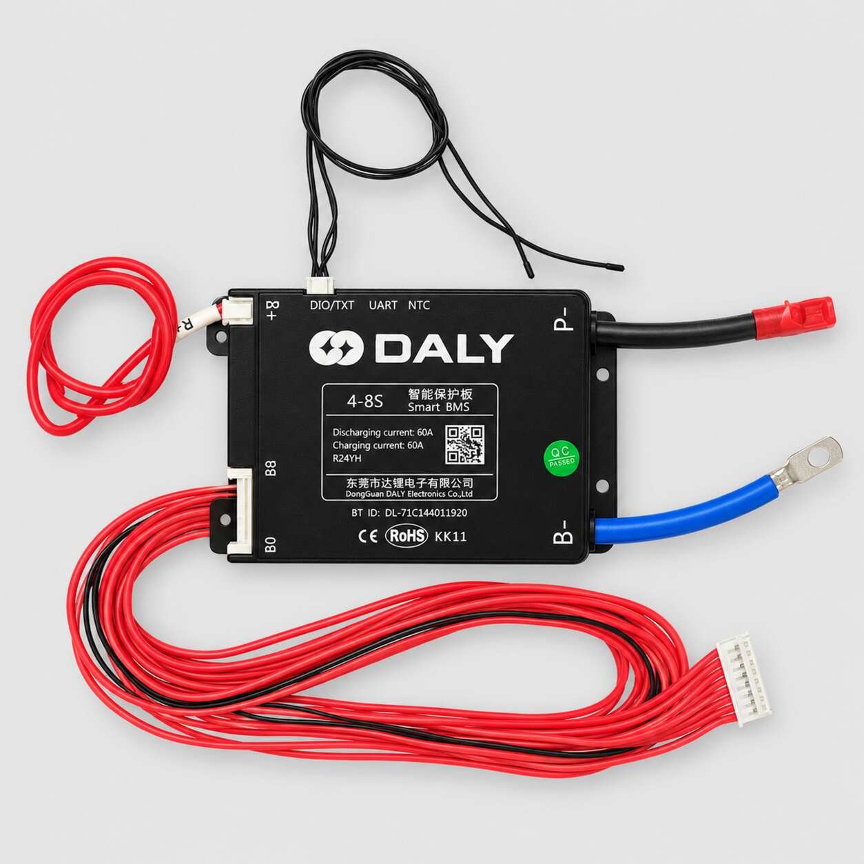
This DALY 4–8S Smart BMS is designed for compatible rechargeable lithium battery packs containing four to eight series-connected cells or parallel cell groups.
The product is rated for 60A charging and 60A discharging. It is supplied with a complete B0–B8 cell-sensing harness, B+ positive-sensing wire, NTC temperature-sensor leads and heavy-duty B− and P− power cables.
A Bluetooth identification number is printed on the enclosure, indicating compatibility with a supported DALY monitoring application. A UART interface is also provided for compatible communication accessories.
The battery chemistry is not stated on the visible product label. Confirm whether the supplied BMS is programmed for LiFePO4, lithium-ion/NMC or another compatible chemistry before installation.
2. Technical Specifications
| Specification |
Details |
| Brand |
DALY |
| Manufacturer |
Dongguan DALY Electronics Co., Ltd. |
| Product type |
Smart Battery Management System |
| Supported configuration |
4S–8S |
| Rated discharge current |
60A |
| Rated charging current |
60A |
| Battery-negative connection |
B− |
| External negative connection |
P− |
| Battery-positive sensing |
B+ |
| Cell-sensing connections |
B0–B8 |
| Cell-sensing harness |
Included |
| Communication interface |
UART |
| Bluetooth identification |
Printed on enclosure |
| Temperature sensing |
NTC sensor leads included |
| Product marking |
R24YH |
| Bluetooth ID |
DL-71C144011920 |
| Cell balancing |
Not specified on the label |
| Balancing current |
Not specified |
| Peak discharge current |
Not specified |
| Protection thresholds |
Configuration-dependent |
| Battery chemistry |
Must be verified |
3. Included Components
The supplied set visibly includes:
- One DALY 4–8S 60A Smart BMS
- One multi-wire B0–B8 cell-sensing harness
- One white multi-pin harness connector
- One B+ positive-sensing wire
- Two black NTC temperature-sensor leads
- One blue B− high-current cable
- One ring terminal fitted to the blue cable
- One black P− high-current cable
- One red insulated terminal fitted to the black cable
- Integrated B8 and B0 sensing connectors
- Protective black enclosure with mounting tabs
4. Voltage Compatibility
The correct battery voltage depends on the selected series configuration and cell chemistry.
| Configuration |
LiFePO4 nominal voltage |
LiFePO4 maximum voltage |
Li-ion/NMC nominal voltage |
Li-ion/NMC maximum voltage |
| 4S |
12.8V |
14.6V |
14.4V–14.8V |
16.8V |
| 5S |
16.0V |
18.25V |
18.0V–18.5V |
21.0V |
| 6S |
19.2V |
21.9V |
21.6V–22.2V |
25.2V |
| 7S |
22.4V |
25.55V |
25.2V–25.9V |
29.4V |
| 8S |
25.6V |
29.2V |
28.8V–29.6V |
33.6V |
These figures are chemistry references only. The charger, cell configuration and BMS protection profile must all match.
5. Main Features
- Configurable operation from 4S to 8S
- 60A rated charging current
- 60A rated discharging current
- Individual cell-group voltage monitoring
- Complete sensing harness supplied
- Bluetooth smart-monitoring identification
- UART communication connection
- Dual NTC temperature sensing
- Separate B− and P− power connections
- B+ positive-sensing connection
- QR code for product information
- CE and RoHS markings
- Protective enclosure with mounting points
- Suitable for new battery construction and compatible repairs
6. Typical Protection Functions
A compatible DALY Smart BMS of this type is generally designed to manage:
- Individual cell overvoltage
- Individual cell undervoltage
- Charging overcurrent
- Discharging overcurrent
- External short circuit
- Charging temperature
- Discharging temperature
- Battery-pack voltage monitoring
- Charge and discharge switching
The exact voltage thresholds, current limits, recovery values, delay times and balancing specifications must be checked through the applicable DALY documentation or compatible application.
7. Connection Guide
B− Cable
The blue heavy-duty cable connects to the main negative terminal of the battery pack.
P− Cable
The black heavy-duty cable provides the external negative connection for the charger and load.
B+ Wire
Connects to the positive end of the complete battery pack for voltage sensing and BMS power.
B0–B8 Harness
Connects to the negative point and individual series-cell junctions according to the selected 4S–8S configuration.
NTC Leads
The two black sensor leads monitor battery temperature and should be positioned securely against suitable locations within the battery pack.
UART Port
Supports compatible DALY communication devices, displays or configuration accessories.
Never determine a connection only from wire colour. Verify all printed terminal markings and follow the wiring diagram for this exact BMS version.
8. Suitable Applications
This Smart BMS may be suitable for compatible battery packs used in:
- Electric bicycles
- Electric scooters
- Robotics and automation
- Portable power systems
- Solar battery storage
- UPS and backup batteries
- Rechargeable tools
- Industrial equipment
- Custom lithium battery packs
- Battery repair and replacement projects
Suitability depends on the programmed chemistry, number of series groups, charger voltage, continuous current and peak-current requirement.
9. Compatibility Checklist
Before purchasing or installing this BMS, verify:
- Factory-programmed battery chemistry
- Required number of series groups
- Nominal battery-pack voltage
- Maximum charging voltage
- Charger chemistry and output voltage
- Required continuous discharge current
- Required peak or motor-starting current
- Maximum charging current
- B0–B8 sensing-wire sequence
- B−, P− and B+ connection arrangement
- Bluetooth-app compatibility
- UART accessory compatibility
- Temperature-sensor requirements
- Physical dimensions and mounting space
A matching 4–8S configuration does not guarantee compatibility. Battery chemistry and protection settings must also match the cells.
10. Installation Guidance
- Confirm the BMS chemistry and required series configuration.
- Measure every battery-group voltage before installation.
- Ensure all series groups are closely voltage-matched.
- Connect B− to the main battery-negative terminal.
- Connect the charger and load negative through P−.
- Connect B+ to the battery-pack positive terminal.
- Install the B0–B8 wires in the correct voltage sequence.
- Verify every adjacent sensing-wire voltage with a multimeter.
- Plug in the sensing harness only after checking the complete sequence.
- Position both NTC sensors firmly against the battery cells.
- Use cables and connectors suitable for the expected current.
- Insulate all exposed terminals and electrical connections.
- Confirm the complete battery voltage before connecting a charger or load.
Incorrect sensing-wire order can permanently damage the BMS.
11. Important Current-Rating Note
The 60A rating must be evaluated together with:
- Battery-cell current capability
- Battery-pack parallel configuration
- Load or motor-controller peak current
- Cable cross-sectional area
- Connector and terminal ratings
- Nickel or copper interconnection capacity
- BMS cooling conditions
- Ambient operating temperature
Confirm both the continuous and peak-current requirements before using the BMS with motors or other high-surge loads.
12. Safety Information
- Do not reverse the battery polarity.
- Do not short-circuit the B− or P− cables.
- Do not connect sensing wires in the wrong sequence.
- Do not use an incompatible charger.
- Do not use the BMS with an unverified battery chemistry.
- Do not exceed the BMS or battery-cell current rating.
- Keep the BMS away from water and conductive debris.
- Do not use a damaged, burnt, corroded or unusually hot BMS.
- Secure the BMS and wiring against vibration and mechanical stress.
- Installation should be performed by a person familiar with lithium battery-pack wiring and safety.