1. Product Overview
This compact protection board is designed for two lithium-ion cells or parallel cell groups connected in series. It is suitable for compatible 3.6V or 3.7V lithium-ion/NMC cells having a maximum charging voltage of 4.2V per cell.
A completed 2S battery pack has a nominal voltage of approximately 7.2V–7.4V and a maximum charging voltage of 8.4V.
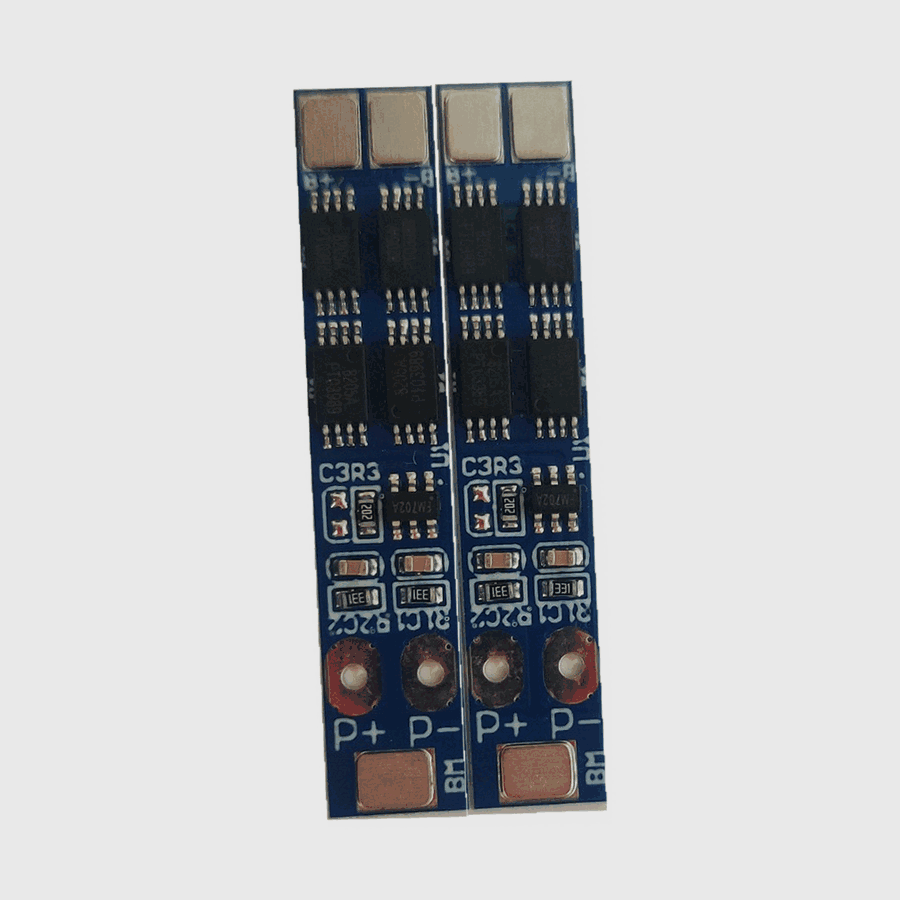
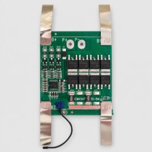
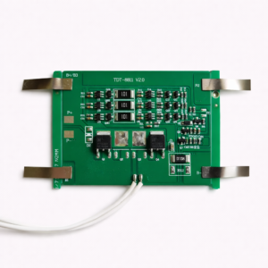
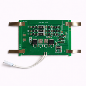
The PCB provides B+, B1 and B− battery connections, along with P+ and P− terminals for connecting the charger and load. Four power MOSFET packages are visible on the board.
The exact current rating, protection thresholds and balancing capability are not printed or verified and should not be assumed from the board’s appearance.
2. Technical Specifications
| Specification |
Details |
| Product type |
Lithium-ion battery protection/BMS board |
| Cell configuration |
2S |
| Compatible chemistry |
Lithium-ion/NMC with 4.2V maximum cell voltage |
| Nominal pack voltage |
7.2V–7.4V |
| Maximum pack charging voltage |
8.4V |
| Maximum cell charging voltage |
4.2V |
| Battery connections |
B+, B1 and B− |
| External power connections |
P+ and P− |
| Port configuration |
Common charge/discharge port |
| Power MOSFET packages |
Four visible |
| Continuous discharge current |
Not specified |
| Peak discharge current |
Not specified |
| Maximum charging current |
Not specified |
| Protection thresholds |
Not specified |
| Cell balancing |
Not verified |
| Bluetooth connectivity |
No |
| Communication interface |
Not provided |
3. Terminal Connections
| Board marking |
Typical function |
| B− |
Negative terminal of the first cell or main battery negative |
| B1/BM |
Junction between the first and second series cells |
| B+ |
Positive terminal of the second cell or main battery positive |
| P+ |
Positive terminal for the charger and load |
| P− |
Negative terminal for the charger and load |
The terminal functions above are based on standard 2S BMS markings. Confirm the exact terminal arrangement with a multimeter or supplier wiring diagram before installation.
4. Main Features
- Designed for two lithium-ion cells or parallel groups connected in series
- Suitable for 7.2V and 7.4V nominal battery packs
- Supports an 8.4V maximum pack-charging voltage
- Separate midpoint connection for monitoring both series groups
- Four visible power MOSFET packages
- Clearly marked P+ and P− external terminals
- Compact narrow PCB construction
- Suitable for battery manufacturing, replacement and repair applications
The board may provide overcharge, over-discharge, overcurrent and short-circuit protection, but the exact functions and activation thresholds must be confirmed before use.
5. Suitable Applications
This BMS may be suitable for compatible 2S lithium-ion battery packs used in:
- Portable electronic equipment
- Rechargeable lighting systems
- Bluetooth speakers
- Small robotics projects
- RC equipment
- DIY electronics
- Backup-power modules
- Battery repair and replacement work
- Custom 7.4V lithium-ion battery assemblies
Suitability depends on the cell chemistry, charging voltage, continuous current, peak current and required protection thresholds.
6. Battery and Charger Compatibility
Before purchasing or installing this board, verify:
- The battery contains exactly two series-connected cell groups
- Each cell has a nominal voltage of 3.6V or 3.7V
- Each cell has a maximum charging voltage of 4.2V
- The charger is designed for a 2S lithium-ion battery
- Charger output does not exceed 8.4V
- Required charge and discharge currents are within the verified board rating
- B+, B1 and B− terminal positions match the battery assembly
- P+ and P− connections match the intended charger and load
- PCB dimensions fit inside the battery enclosure
This board is not suitable for 2S LiFePO4 batteries because LiFePO4 cells require different charging and protection-voltage thresholds.
7. Installation Guidance
- Check the voltage of both cell groups before connecting the board.
- Ensure that the two series groups are closely voltage-matched.
- Identify B−, B1/BM and B+ before making any connection.
- Connect B− to the main battery-negative terminal.
- Connect B1/BM to the junction between the two series groups.
- Connect B+ to the main battery-positive terminal.
- Connect the charger and load through P+ and P−.
- Verify the intermediate and total pack voltages with a multimeter.
- Insulate the PCB and all exposed electrical connections.
- Confirm the protected output voltage before connecting equipment.
8. Important Current-Rating Note
The current rating cannot be determined reliably from the board dimensions or number of MOSFETs alone.
Confirm the following before use:
- Maximum continuous discharge current
- Short-duration peak current
- Maximum charging current
- Overcurrent-protection threshold
- Short-circuit-protection behaviour
- MOSFET and PCB temperature limits
- Required output-wire and connection-strip capacity
Do not advertise or operate this board at a particular amperage unless its rating has been confirmed by the supplier or through controlled testing.
9. Quantity Note
The supplied photograph shows two identical protection boards. Confirm whether the selling quantity is one board or two boards before publishing the final listing quantity.
10. Safety Information
- Incorrect B1/BM wiring can permanently damage the protection board.
- Never connect the battery terminals in the wrong sequence.
- Do not reverse the battery polarity.
- Do not short-circuit the terminals.
- Use only a compatible 8.4V lithium-ion charger.
- Do not exceed the verified current rating of the board or cells.
- Keep the PCB away from water, conductive dust and loose metal objects.
- Do not use a burnt, cracked, corroded or unusually hot board.
- Battery assembly should be performed by someone familiar with lithium-ion battery wiring and safety.