1. Product Overview
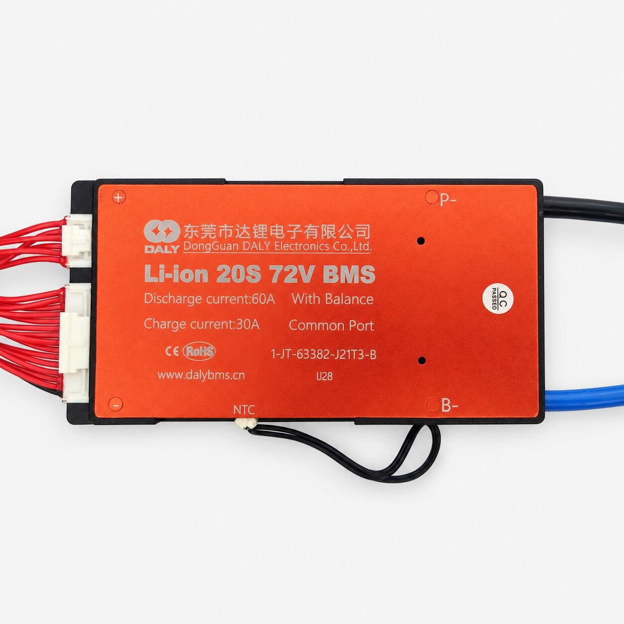
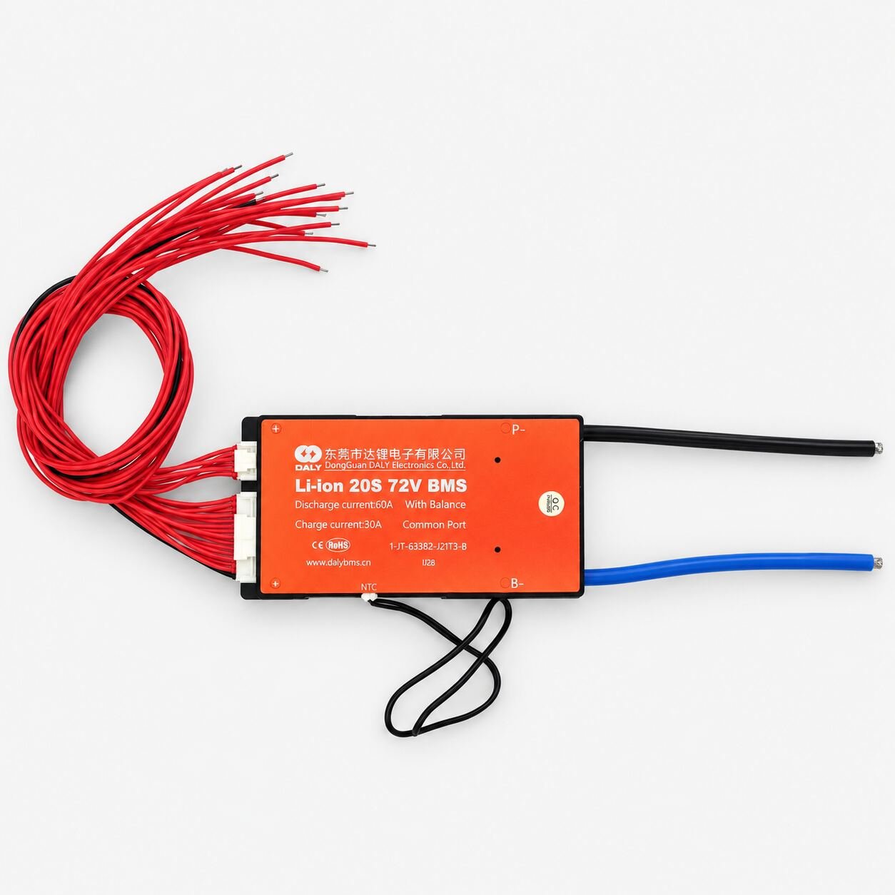
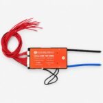
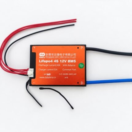
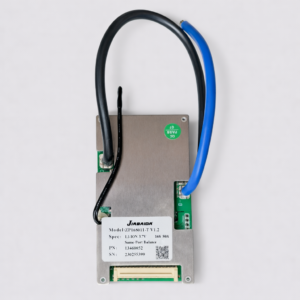
The DALY 20S 72V 60A BMS is a battery management and protection system designed for twenty lithium-ion cells or parallel cell groups connected in series.
A 20S lithium-ion battery pack has a nominal voltage of approximately 72V and reaches 84V when fully charged. Such batteries are commonly marketed as 72V lithium-ion or NMC battery packs.
This BMS monitors all twenty series-connected cell groups and disconnects the battery when unsafe charging, discharging, temperature or current conditions are detected.
The product label specifies a 60A discharge-current rating and a 30A charging-current rating. It uses a common-port configuration and includes cell balancing and an NTC temperature sensor.
2. Technical Specifications
| Specification |
Details |
| Brand |
DALY |
| Model |
1-JT-63382-J21T3-B |
| Product code |
IJ28 |
| Product type |
Lithium-ion battery protection BMS |
| Cell configuration |
20S |
| Battery chemistry |
Lithium-ion/NMC |
| Compatible cell voltage |
3.6V or 3.7V nominal |
| Nominal pack voltage |
72V–74V |
| Battery class |
72V lithium-ion |
| Maximum charging voltage |
84V |
| Advertised discharge current |
60A |
| Advertised charging current |
30A |
| Port configuration |
Common port |
| Cell balancing |
Yes |
| Temperature monitoring |
Yes, NTC sensor supplied |
| Cell-voltage monitoring |
Twenty series-connected groups |
| Protection functions |
Overcharge, over-discharge, overcurrent, short circuit and temperature |
| Balance-wire connectors |
Two connectors visible |
| External negative connection |
P− cable |
| Battery-negative connection |
B− cable |
| Communication interface |
Not provided |
| Bluetooth connectivity |
Not provided |
| Installation type |
Battery-pack integrated |
| Charger requirement |
20S lithium-ion charger with maximum output of 84V |
Protection thresholds, balancing current, recovery delay and peak-current capability should be confirmed from DALY’s specification for the exact model before use.
3. Visible Connection Points
| Connection |
Typical function |
| B− |
Connects to the battery pack’s main negative terminal |
| B1–B19 |
Connect sequentially to the intermediate cell-group junctions |
| B+ or B20 |
Connects to the final cell group or battery-pack positive terminal as specified |
| P− |
Common negative connection for the load and charger |
| P+ |
External positive connection, normally connected directly to battery positive |
| NTC |
Temperature-sensor connection |
| Balance connectors |
Connect the twenty individual cell-group sensing points to the BMS |
The exact balance-wire sequence must be verified using the wiring diagram supplied for this model. Do not identify sensing wires only by colour, connector position or wire length.
4. Protection and Management Functions
The DALY 20S BMS is intended to provide essential protection and monitoring for a compatible lithium-ion battery pack, including:
- Monitoring of twenty series-connected cell groups
- Individual cell overcharge protection
- Individual cell over-discharge protection
- Discharge-overcurrent protection
- Short-circuit protection
- Charging and discharging through a common negative port
- Temperature monitoring through the supplied NTC sensor
- Passive cell balancing
- Charge and discharge switching through internal MOSFETs
- Recovery after supported protection events
Cell balancing helps reduce voltage differences between the series groups. However, a BMS cannot repair damaged, severely mismatched or deeply discharged cells.
5. Suitable Applications
This BMS may be suitable for compatible 20S lithium-ion battery packs used in:
- Electric scooters
- Electric motorcycles
- E-rickshaws and mobility equipment
- High-voltage robotics projects
- Electric utility vehicles
- Portable power systems
- Battery-powered industrial equipment
- Custom 72V lithium-ion battery packs
- Battery repair and replacement projects
- Medium-current traction-battery applications
The continuous current and startup current of the connected equipment must remain within the verified capability of the BMS, battery cells, cables and connectors.
6. Battery and Charger Compatibility
Use this BMS only when:
- The battery contains exactly twenty series-connected lithium-ion cell groups.
- Each cell group has a nominal voltage of approximately 3.6V or 3.7V.
- Each cell has a maximum charging voltage of 4.2V.
- The complete pack has a nominal voltage of approximately 72V–74V.
- The charger is designed specifically for a 20S lithium-ion battery.
- The charger’s maximum output voltage does not exceed 84V.
- All twenty cell groups are at closely matched voltages before installation.
- The battery cells can safely supply the required continuous and peak current.
- The load’s continuous current remains within the verified system limit.
- The charger output current does not exceed the BMS and battery charging limit.
Do not use this BMS with a 20S LiFePO₄ battery pack. LiFePO₄ cells require different charging and protection-voltage thresholds.
7. Installation Guidance
- Measure the voltage of all twenty cell groups before installation.
- Confirm the correct sensing-wire sequence from the supplied wiring diagram.
- Connect B− to the battery-pack negative terminal.
- Connect each balance wire sequentially to its correct cell-group junction.
- Verify the voltage between every pair of consecutive balance wires.
- Connect the final sensing wire or B+ connection as specified.
- Plug the balance connectors into the BMS only after every voltage has been verified.
- Connect the load and charger negative terminals through P−.
- Connect the external positive terminal directly to battery positive unless the supplied diagram specifies otherwise.
- Position the NTC sensor where it can accurately monitor the battery-cell temperature.
- Use cables, lugs and connectors rated for the required current and voltage.
- Install a correctly rated fuse close to the battery’s positive terminal.
- Insulate every exposed electrical connection.
- Mount the BMS securely where it has adequate ventilation.
- Keep the BMS away from metal surfaces unless suitable electrical insulation is installed.
Incorrect balance-wire order can permanently damage the BMS.
8. Important Current-Rating Note
The 60A BMS rating does not increase the current capability of the battery cells.
The safe operating current of the complete battery system is determined by the lowest-rated component, including:
- Battery cells
- BMS
- Nickel strips or busbars
- Power cables
- Cable lugs
- Connectors
- Fuse
- Charger
- Connected load
Motors and other inductive loads may draw a startup or surge current substantially higher than their normal operating current.
Confirm both the continuous and peak-current requirements before selecting this BMS. Adequate heat dissipation is also necessary when operating near its rated current.
9. Safety Information
- Use only with a compatible 20S lithium-ion battery pack.
- Use only an 84V charger designed for 20S lithium-ion batteries.
- Never use a LiFePO₄ or lead-acid charging profile unless its suitability is professionally verified.
- Never reverse the battery polarity.
- Never short the battery or BMS power terminals.
- Do not connect the balance wires in the wrong order.
- Do not plug in the balance connectors before checking every sensing voltage.
- Do not exceed the 60A advertised discharge-current rating.
- Do not exceed the 30A advertised charging-current rating.
- Use a suitable fuse and correctly rated high-voltage cables.
- Keep the BMS away from water, conductive dust and loose metal objects.
- Do not use damaged, burnt, corroded or unusually hot components.
- Stop using the battery if any cell group becomes swollen, overheated or abnormally unbalanced.
- A 20S battery can produce dangerous voltage and very high fault current.
- Installation should be performed by someone experienced with high-voltage lithium-ion battery systems.