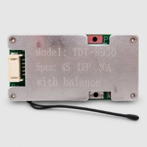
1. Product Overview
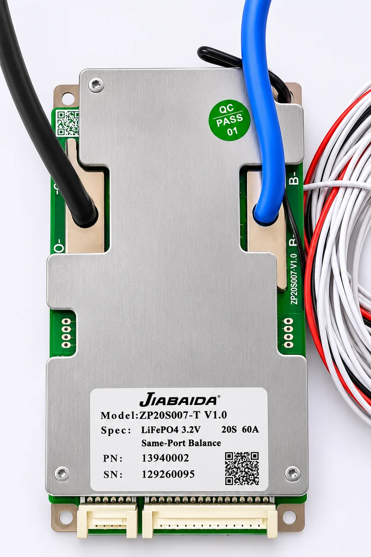
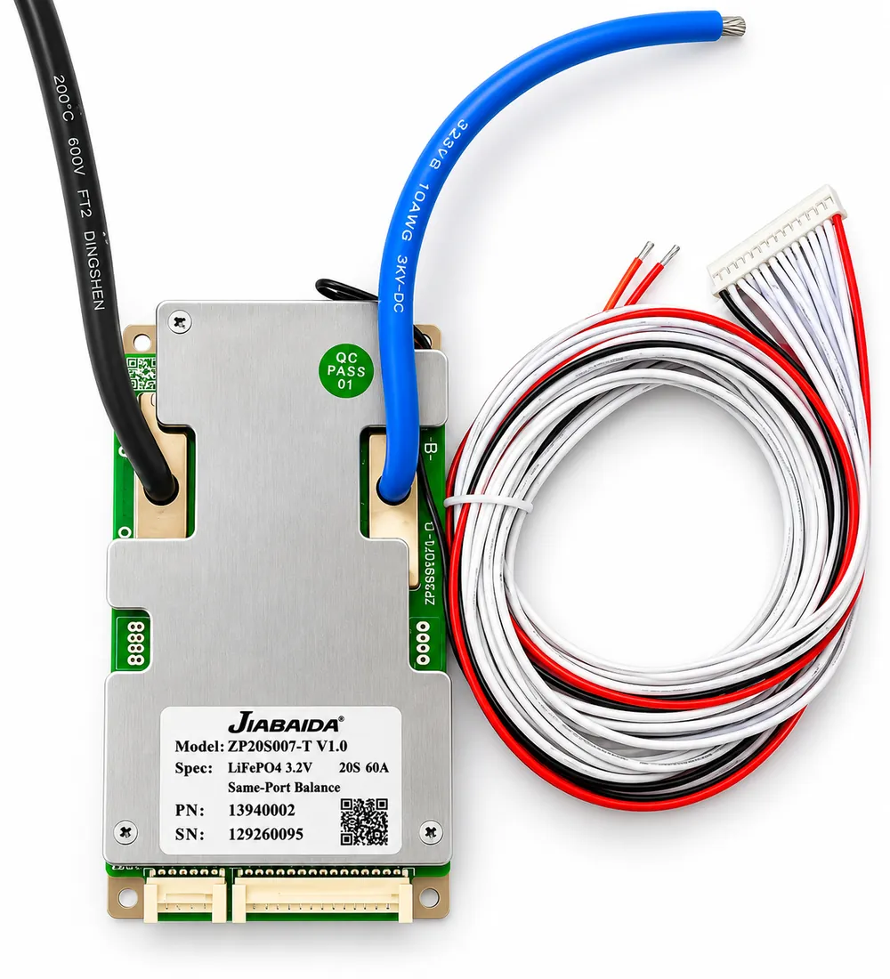
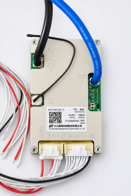
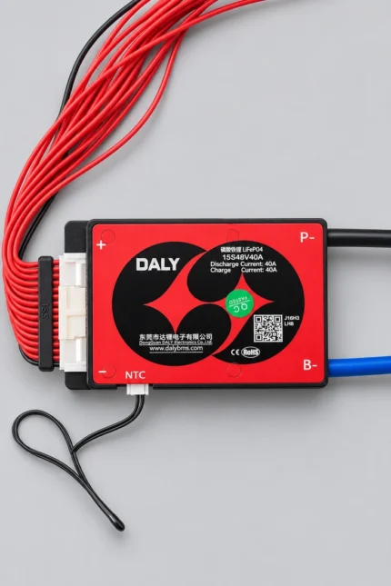
The JBD Jiabaida ZP20S007-T V1.0 20S 60A BMS is a hardware Battery Management System designed for 20-series LiFePO₄ battery packs.
The actual unit is marked:
- Brand: JBD / JIABAIDA
- Model: ZP20S007-T V1.0
- Battery Chemistry: LiFePO₄ / LFP
- Cell Nominal Voltage: 3.2V
- Configuration: 20S
- Current Rating: 60A
- Port Type: Same-Port
- Balancing: Built-in balancing
It provides essential battery protection while monitoring the 20 series cell groups during charging and discharging.
2. Main Specifications
- Battery Chemistry: LiFePO₄ / LFP
- Series Configuration: 20S
- Nominal Cell Voltage: 3.2V
- Nominal Pack Voltage: 64V
- Continuous Current Rating: 60A
- Port Configuration: Same Port / Common Port
- Balancing: Passive Cell Balancing
- BMS Type: Hardware BMS
- Construction: PCB with protective metal cover
- Operating Temperature: Approx. -20°C to +75°C
- Application Class: High-capacity LiFePO₄ battery packs
Nominal Battery Voltage
20 × 3.2V = 64V
For charging voltage, always follow the specification of the actual LiFePO₄ cells and charger used in the battery pack.
3. 60A Continuous Current Rating
The BMS is designed for applications requiring up to 60A continuous battery current.
This makes it suitable for medium- to high-power battery systems such as:
- Electric scooters
- Electric motorcycles
- Electric three-wheelers
- Solar storage batteries
- Inverter batteries
- UPS backup systems
- Industrial battery packs
- Custom LiFePO₄ energy-storage systems
The safe current capability of the completed pack also depends on the cells, busbars, cables, connectors and fuse used.
4. Same-Port Charge & Discharge
This BMS uses a same-port / common-port design.
Charging and discharging are controlled through the same main current path.
Advantages include:
- Simpler battery-pack wiring
- Fewer high-current connections
- Convenient integration in EV and ESS battery packs
- Compact pack design
5. Built-in Cell Balancing
The ZP20S007-T includes passive balancing for the 20 series cell groups.
Balancing helps:
- Reduce voltage differences between cells
- Improve pack consistency
- Prevent one cell group reaching protection voltage significantly before the others
- Improve usable battery capacity
- Support stable long-term pack operation
Balanced cells are particularly important in high-voltage battery packs containing many cells in series.
6. Battery Protection Functions
The BMS provides multiple protection functions including:
- Cell overcharge protection
- Cell over-discharge protection
- Charge over-current protection
- Discharge over-current protection
- Short-circuit protection
- High-temperature protection
- Low-temperature monitoring/protection depending on configuration
- Cell balancing
- Cell-voltage monitoring
When an unsafe condition is detected, the BMS can interrupt the relevant current path to help protect the battery pack.
7. Temperature Monitoring
The BMS incorporates temperature monitoring as part of its battery-protection system.
Temperature protection helps protect the:
- Battery cells
- BMS MOSFETs
- Internal wiring
- High-current connections
The temperature sensor should be positioned correctly inside the battery pack for accurate monitoring.
8. Hardware BMS Design
This is primarily a hardware protection BMS.
It is designed to operate automatically without requiring a mobile application for normal battery protection.
Benefits include:
- Simple operation
- Low standby consumption
- No app required
- Automatic protection
- Compact design
- Suitable for production battery packs and replacements
Do not assume Bluetooth, CAN or RS485 connectivity unless the specific supplied version includes those features.
9. Suitable Applications
The 20S 60A LiFePO₄ BMS is suitable for compatible battery packs used in:
- Electric scooters
- Electric motorcycles
- E-rickshaws
- Electric three-wheelers
- Solar energy-storage systems
- Home ESS batteries
- Inverter battery systems
- UPS backup systems
- Robotics
- AGVs
- Industrial battery systems
- Custom LiFePO₄ battery packs
10. 64V LiFePO₄ Battery Configuration
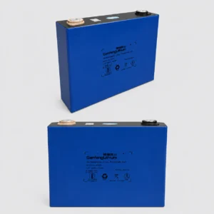
A 20S LiFePO₄ battery contains 20 cells or parallel cell groups connected in series.
With a nominal cell voltage of approximately 3.2V:
20 × 3.2V = 64V nominal
This type of battery is commonly used where a higher-voltage LFP system is required for EV or stationary energy-storage applications.
11. Compatibility Check Before Ordering
Before purchasing this BMS, confirm:
- Battery chemistry is LiFePO₄ / LFP
- Cell nominal voltage is approximately 3.2V
- Battery configuration is exactly 20S
- Nominal pack voltage is approximately 64V
- Required continuous current is within 60A
- Same-port wiring suits the battery design
- Balance harness matches the 20S pack
- Charger voltage matches the actual LiFePO₄ cell specification
Do not select a BMS only by voltage.
The chemistry, number of series cells and current rating must all match the battery pack.
12. Installation Guidelines
Correct balance-wire installation is critical.
Before connecting the BMS:
- Measure every cell-group voltage
- Confirm all 20 series groups
- Verify balance-wire sequence
- Check voltage progressively from battery negative through each sense wire
- Verify B- and output connections
- Use appropriately rated cables and connectors
- Insulate exposed high-current joints
- Secure the BMS against vibration
- Position the temperature sensor correctly
Do not connect the balance connector until the complete wiring sequence has been verified.
13. Important Safety Note
Do not:
- Use this BMS with NMC cells
- Use with an incorrect number of series cells
- Reverse battery polarity
- Connect the balance harness incorrectly
- Exceed the BMS current rating
- Short the battery terminals
- Operate with damaged cells or wiring
- Install where conductive debris or moisture can reach the PCB
Professional installation is recommended for high-capacity lithium battery packs.