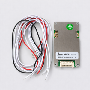
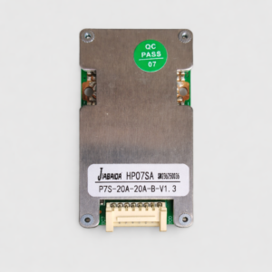
1. Product Overview
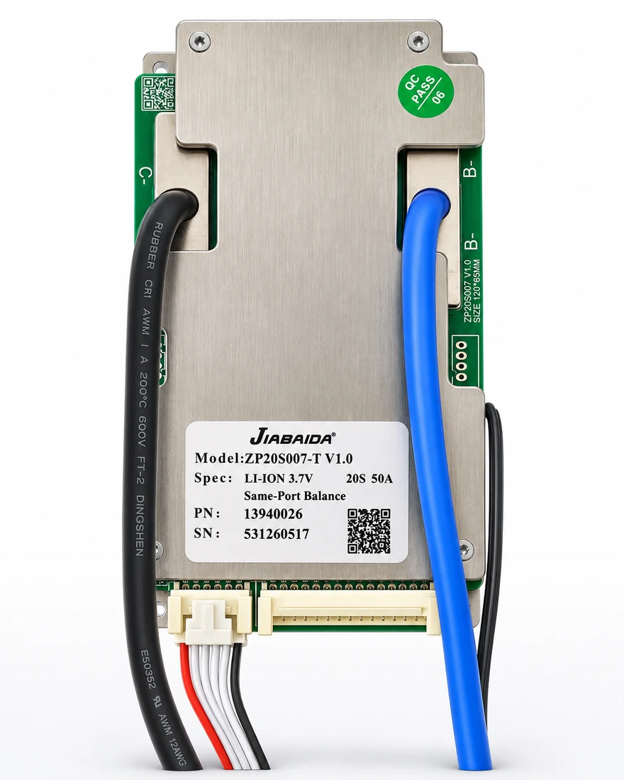
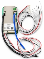
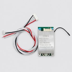
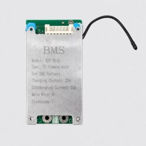
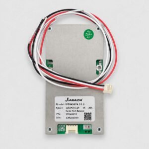
The JBD JIABAIDA ZP20S007-T V1.0 20S 50A BMS is a hardware Battery Management System designed for high-voltage lithium-ion battery packs.
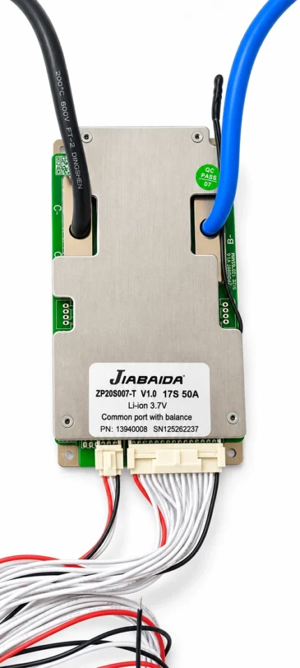
The supplied unit is specifically marked:
- Model: ZP20S007-T V1.0
- Battery Chemistry: Li-ion 3.7V
- Series Configuration: 20S
- Current Rating: 50A
- Port Type: Same-Port
- Balancing: Integrated cell balancing
A 20S Li-ion battery pack has a nominal voltage of approximately 74V and reaches approximately 84V when fully charged.
2. Electrical Specifications
- Brand: JBD / JIABAIDA
- Model: ZP20S007-T V1.0
- Battery Chemistry: Li-ion / NMC
- Cell Nominal Voltage: 3.7V
- Series Configuration: 20S
- Nominal Pack Voltage: Approx. 74V
- Maximum Pack Charge Voltage: Approx. 84V
- Continuous Charge Current: 50A
- Continuous Discharge Current: 50A
- Port Configuration: Same-Port / Common Port
- Quiescent Consumption: ≤60µA
- Circuit Resistance: ≤10mΩ
- Operating Temperature: -20°C to +75°C
3. Same-Port Charge & Discharge
This BMS uses a same-port design, meaning charging and discharging use the same controlled current path.
This simplifies battery pack wiring and makes the BMS suitable for EV and general-purpose lithium battery assemblies where a common charge/discharge connection is preferred.
4. Built-in Cell Balancing
The ZP20S007 includes integrated cell balancing to help reduce voltage differences between cells in the battery pack.
Balance Specifications
- Balance Type: Pulse balancing
- Typical Balance Start Voltage: Approx. 3.90V per cell
- Typical Balance Current: Approx. 50mA
- Specified Balance Current Range: 40–60mA
Cell balancing helps maintain more uniform cell voltages during charging and supports better overall pack performance.
5. Battery Protection Functions
The BMS provides important protection functions for the lithium battery pack, including:
- Cell overcharge protection
- Cell over-discharge protection
- Charging over-current protection
- Discharging over-current protection
- Two-stage discharge over-current protection
- Short-circuit protection
- Charge over-temperature protection
- Charge low-temperature protection
- Discharge over-temperature protection
- Discharge low-temperature protection
- MOSFET temperature protection
- Cell balancing
- Cell sensing / disconnection protection
These protections help isolate the battery when abnormal electrical or temperature conditions are detected.
6. Cell Voltage Protection
For the NMC/Li-ion configuration, the manufacturer’s specification provides approximately:
- Typical Overcharge Protection: 4.25V per cell
- Typical Overcharge Recovery: 4.15V per cell
- Typical Over-discharge Protection: 2.70V per cell
- Typical Over-discharge Recovery: 2.90V per cell
These values are BMS protection thresholds and should not be confused with the recommended normal operating voltage range of the battery cells.
7. 50A Current Protection Configuration
For the 50A version, the manufacturer’s specification gives:
- Continuous Current: 50A
- Charge Over-current Protection: 95A ±20A
- Stage-1 Discharge Over-current Protection: 95A ±20A
- Stage-2 Discharge Over-current Protection: 380A ±30A
- Short-Circuit Protection Reference: 760A ±50A
The BMS should still be selected so that the battery pack’s normal working current remains within the 50A continuous rating.
8. Physical Specifications
- PCB Length: Approx. 120mm
- PCB Width: Approx. 65mm
- PCB Height: Approx. 14mm
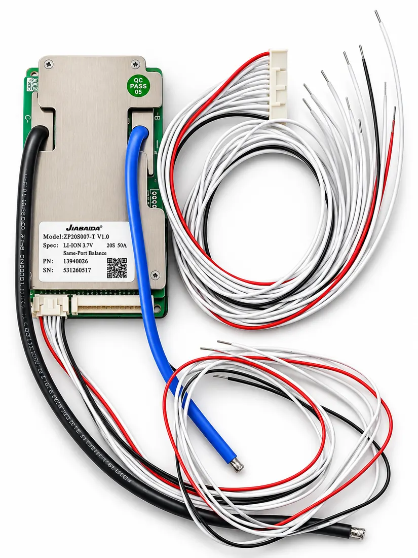
- Construction: PCB with protective metal cover
- Balance/Sense Harness: Multi-wire cell sensing harness
- Heavy Current Connections: High-current cable connections
Dimensions refer to the BMS structure itself and may not include the full cable and wiring harness.
9. Suitable Applications
Suitable for compatible 20S 72V-class Li-ion / NMC battery packs used in:
- Electric scooters
- Electric motorcycles
- E-rickshaws
- Electric three-wheelers
- Light electric vehicles
- Robotics
- Custom EV battery packs
- Industrial lithium battery packs
- High-voltage DIY lithium battery systems
10. Battery Voltage Configuration
For a 20S NMC / Li-ion battery:
Nominal Voltage
20 × 3.7V = 74V
Maximum Charge Voltage
20 × 4.2V = 84V
This is commonly referred to in the EV market as a 72V lithium battery system.
11. Compatibility Check Before Ordering
Before purchasing, confirm:
- Battery chemistry is Li-ion / NMC
- Pack configuration is 20S
- Battery is in the 72V / 74V nominal class
- Maximum charge voltage is approximately 84V
- Required continuous current is within 50A
- Same-port wiring is suitable for your battery design
- Balance-wire sequence matches the battery pack
Do not select a BMS only based on battery voltage. Cell chemistry, series count and current rating must all match.
12. Installation Note
Correct balance-wire connection is essential.
- Confirm the complete 20S cell sequence before connecting the BMS
- Measure every series voltage before plugging in the balance harness
- Do not reverse B- or current connections
- Do not connect balance wires in the wrong order
- Insulate all exposed high-current terminals properly
- Use appropriately sized cables and connectors for the required current
Professional installation is recommended for high-voltage EV battery packs.
13. Safety Note
Do not:
- Use the BMS with the wrong battery chemistry
- Connect it to a different series configuration
- Exceed its continuous-current rating
- Reverse battery polarity
- Short the battery terminals
- Connect the balance harness incorrectly
- Use damaged cells or damaged wiring
Always verify cell voltages and wiring before powering the completed battery pack.