1. Product Overview
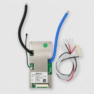
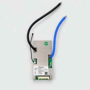
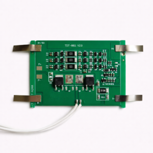
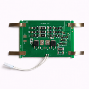
The TDT-8930B-4S is a compact battery-protection BMS board designed for battery packs containing four series-connected lithium cell groups.
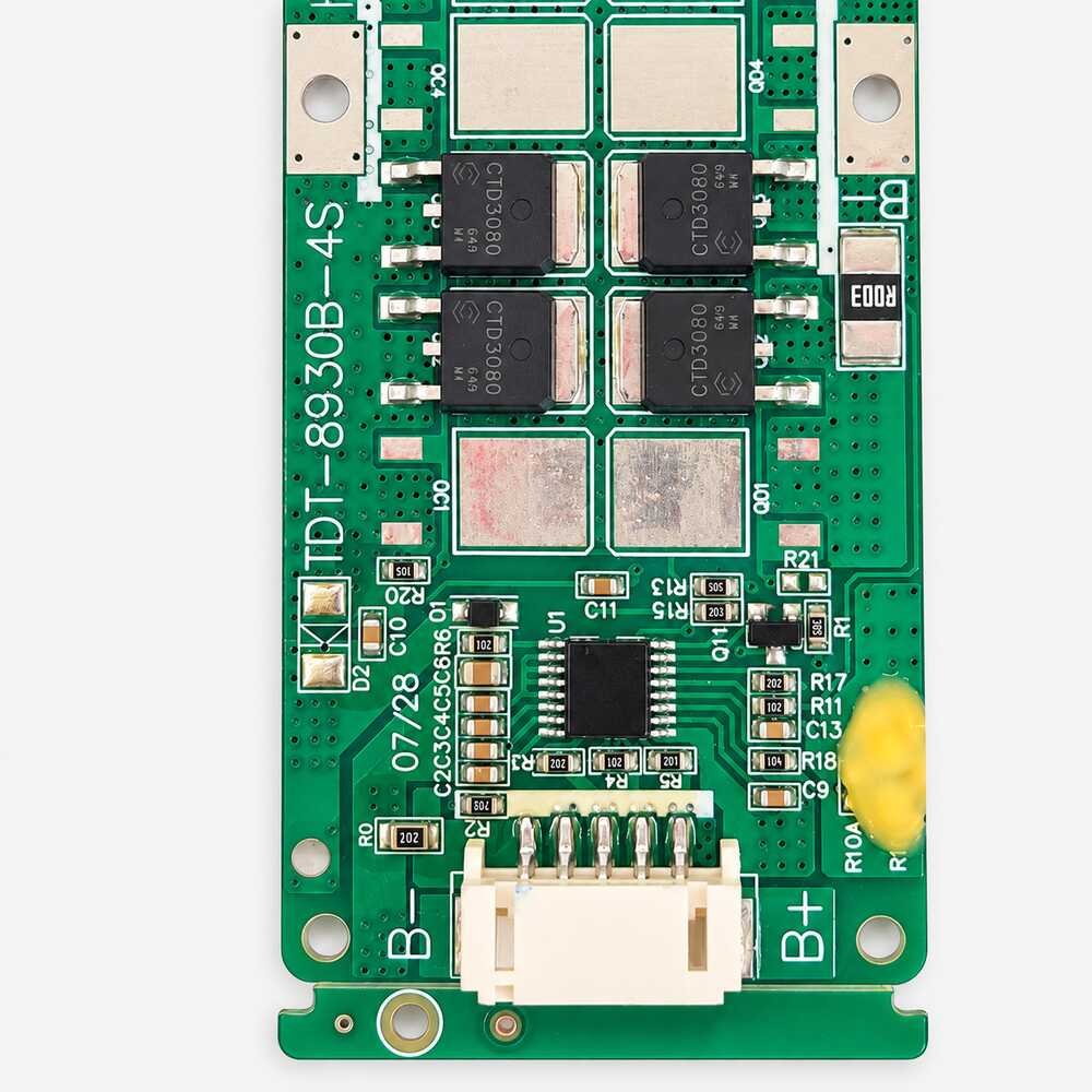
The PCB is marked TDT-8930B-4S, confirming its 4S configuration. The current rating is not printed on the visible side of the board; however, the supplier bill identifies this model as a 10A BMS.
The board monitors the voltage of the four series groups and is intended to disconnect the battery during unsafe charging, excessive discharge, overcurrent or short-circuit conditions.
The battery chemistry is not marked on the PCB. Compatibility with LiFePO₄ or conventional 3.6V/3.7V lithium-ion cells must therefore be confirmed before installation.
2. Technical Specifications
| Specification |
Details |
| Model |
TDT-8930B-4S |
| Product type |
Lithium battery protection BMS board |
| Cell configuration |
4S |
| Advertised current rating |
10A, according to supplier bill |
| Current marking on PCB |
Not visible |
| Battery chemistry |
Not specified; verify before use |
| Nominal pack voltage |
Depends on battery chemistry |
| Maximum charging voltage |
Depends on battery chemistry |
| Power MOSFETs |
Four CTD3080 MOSFETs visible |
| Protection functions |
Overcharge, over-discharge, overcurrent and short circuit |
| Cell-voltage monitoring |
Four series-connected cell groups |
| Cell balancing |
Not confirmed |
| Temperature monitoring |
Not visible or specified |
| Communication interface |
Not provided |
| Bluetooth connectivity |
Not provided |
| Construction |
Open PCB |
| Installation type |
Battery-pack integrated |
Protection thresholds, balancing current, overcurrent limits, recovery behaviour and delay times should be confirmed from the supplier or manufacturer before use.
3. Voltage Compatibility
The correct operating voltage depends on the battery chemistry:
| Battery chemistry |
Cell voltage |
Nominal 4S pack voltage |
Maximum charging voltage |
| LiFePO₄ |
3.2V nominal |
12.8V |
14.6V |
| Lithium-ion/NMC |
3.6V–3.7V nominal |
14.4V–14.8V |
16.8V |
Do not select the chemistry solely from the board’s 4S marking. A 4S LiFePO₄ BMS and a 4S lithium-ion BMS use different protection-voltage thresholds.
4. Visible Components and Connections
| Visible marking or component |
Description |
| TDT-8930B-4S |
PCB model and 4S configuration |
| B− |
Battery-pack negative connection |
| B+ |
Battery-pack positive connection |
| White connector |
Cell-group sensing or balance-wire connector |
| CTD3080 |
Marking visible on four power MOSFETs |
| R003 |
Low-resistance current-sensing components |
| U1 |
Battery-protection control IC |
| 07/28 |
PCB production or revision marking; exact meaning not confirmed |
The full charge and discharge terminal arrangement is not completely visible in the supplied image. Confirm every connection using the correct wiring diagram before installation.
5. Protection Functions
The TDT-8930B-4S is intended to provide essential protection for a compatible 4S battery pack, including:
- Individual cell-group voltage monitoring
- Overcharge protection
- Over-discharge protection
- Discharge-overcurrent protection
- Short-circuit protection
- Charge and discharge control through onboard MOSFETs
- Recovery after supported protection events
Cell-balancing capability is not confirmed from the visible PCB markings and should not be advertised unless verified by the supplier.
6. Suitable Applications
This BMS may be suitable for compatible low-current 4S lithium battery packs used in:
- Rechargeable LED lights
- Portable electronic equipment
- Small backup-power devices
- DIY battery packs
- Robotics projects
- Battery-powered instruments
- Toys and hobby equipment
- Small solar applications
- Battery repair and replacement projects
- Other equipment operating within the verified 10A limit
The load’s continuous current and startup current must remain within the verified capability of the BMS and battery cells.
7. Battery and Charger Compatibility
Use this board only when:
- The battery contains exactly four series-connected cell groups.
- The battery chemistry matches the BMS protection thresholds.
- The charger is designed for the same cell configuration and chemistry.
- The charger voltage does not exceed the battery pack’s permitted maximum.
- All four cell groups are at closely matched voltages before connection.
- The battery cells can safely supply the required current.
- The load’s continuous and peak current remain within the verified BMS limit.
Use a maximum 14.6V charger for a 4S LiFePO₄ pack or a maximum 16.8V charger for a 4S 4.2V lithium-ion pack. Do not interchange these chargers.
8. Installation Guidance
- Confirm the battery chemistry before installation.
- Measure all four cell-group voltages individually.
- Obtain the correct wiring diagram for the TDT-8930B-4S.
- Connect B− to the battery-pack negative terminal.
- Connect the sensing wires sequentially to the four series groups.
- Connect B+ to the battery-pack positive terminal as specified.
- Verify the voltage between every consecutive sensing wire before inserting the connector.
- Use properly sized wires for the expected current.
- Keep soldering time short to avoid overheating the PCB and battery cells.
- Insulate the board and every exposed electrical connection.
- Prevent the PCB from touching nickel strips, metal enclosures or other conductive parts.
- Test the completed pack at a low current before connecting the final load.
Incorrect sensing-wire order can permanently damage the BMS.
9. Important Current and Safety Information
The 10A BMS rating does not increase the current capability of the battery cells.
The safe current of the complete battery pack is determined by its lowest-rated component, including:
- Battery cells
- BMS
- Nickel strips or busbars
- Output wires
- Connectors
- Fuse
- Charger
- Connected load
Always observe the following precautions:
- Do not reverse the battery polarity.
- Do not short B+, B− or any output terminals.
- Do not connect the sensing wires in the wrong sequence.
- Do not exceed the verified 10A current rating.
- Do not use an incompatible battery charger.
- Keep the PCB away from water, conductive dust and loose metal objects.
- Do not use a burnt, cracked, corroded or unusually hot board.
- Install an appropriately rated fuse in the completed battery pack.
- Installation should be performed by someone familiar with lithium-battery wiring and safety.