1. Product Overview
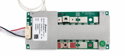
The JBD DB24SA03 is a smart battery-management system designed for compatible multi-series LiFePO₄ and NMC lithium-ion battery packs.
This 60A version provides battery monitoring, protection, cell balancing and communication through Bluetooth and UART. Users can connect the BMS to the compatible JBD or Xiaoxiang mobile application to view important battery information such as individual cell voltages, total pack voltage, current, temperature, state of charge and active protection status.
The common-port design uses the same power connection for charging and discharging. Its wide series compatibility makes it suitable for customised battery packs used in electric vehicles, energy-storage systems and other medium-current applications.
2. Technical Specifications
| Specification |
Details |
| Brand |
JBD / Jiabaida |
| Model |
DB24SA03 |
| Product type |
Smart lithium battery-management system |
| LiFePO₄ compatibility |
7S–24S |
| NMC Li-ion compatibility |
7S–20S |
| Continuous-current rating |
60A |
| Charging and discharging |
Common port |
| Cell balancing |
Yes, passive balancing |
| Bluetooth |
Built in |
| Mobile application |
JBD BMS / Xiaoxiang BMS app |
| Wired communication |
UART |
| PC connectivity |
Supported using a compatible UART adaptor |
| Cell-voltage monitoring |
Yes |
| Pack-current monitoring |
Yes |
| State-of-charge display |
Supported through the app |
| Temperature monitoring |
Yes |
| Protection parameters |
Configurable within supported limits |
| Balance-wire harness |
Included |
| Cooling construction |
Metal heat-dissipation plates |
| RS485 communication |
Not included unless specified |
| CAN communication |
Not included unless specified |
| Waterproof rating |
Not specified |
| Part number shown |
17270019 |
| Communication marking |
UART |
| MAC address |
Unique to each BMS |
3. Battery Voltage Compatibility
The final operating voltage depends on the selected chemistry and number of series-connected cell groups.
LiFePO₄ Examples
| Configuration |
Nominal Pack Voltage |
Typical Full-Charge Voltage |
| 8S |
25.6V |
29.2V |
| 12S |
38.4V |
43.8V |
| 15S |
48V |
54.75V |
| 16S |
51.2V |
58.4V |
| 24S |
76.8V |
87.6V |
NMC Li-ion Examples
| Configuration |
Nominal Pack Voltage |
Maximum Charging Voltage |
| 7S |
25.9V |
29.4V |
| 10S |
37V |
42V |
| 13S |
48.1V |
54.6V |
| 14S |
51.8V |
58.8V |
| 20S |
74V |
84V |
Always select the correct charger for the battery chemistry and series configuration.
4. Smart Monitoring Functions
The Bluetooth connection allows compatible smartphones to access available battery information through the JBD or Xiaoxiang BMS application.
Depending on the configuration and firmware, the application may display:
- Total battery voltage
- Individual cell-group voltage
- Charge and discharge current
- Remaining battery percentage
- Battery capacity information
- BMS temperature
- External sensor temperatures
- Charge MOSFET status
- Discharge MOSFET status
- Cell-balancing status
- Protection alarms
- Battery cycle information
- Historical battery data
- Voltage difference between cell groups
Some protection and capacity parameters can be configured through the application or JBD computer software. Settings should only be changed by someone familiar with lithium-battery systems.
5. Protection Functions
The JBD DB24SA03 is intended to provide essential protection for a correctly assembled and configured battery pack, including:
- Cell overcharge protection
- Cell over-discharge protection
- Charge overcurrent protection
- Discharge overcurrent protection
- Short-circuit protection
- Charging-temperature protection
- Discharging-temperature protection
- MOSFET-temperature protection
- Individual cell-voltage monitoring
- Passive cell balancing
- Charge and discharge MOSFET control
- Protection-event monitoring through the app
Exact protection thresholds depend on the battery chemistry, firmware and programmed settings.
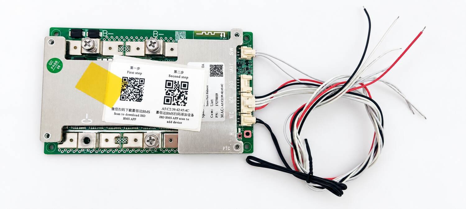
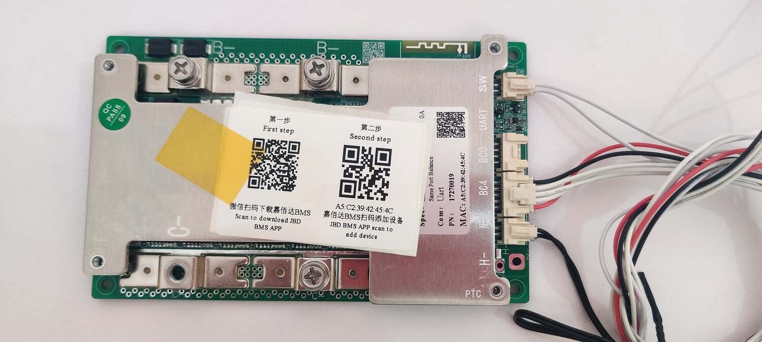
6. Visible Connections and Ports
| PCB Marking or Connection |
Typical Function |
| B− |
Battery-pack negative connection |
| Balance-wire connectors |
Cell-group voltage-sensing connections |
| UART |
Wired data communication or compatible external accessory |
| SW |
External power or activation switch connection |
| NTC wires |
Battery-temperature sensing |
| BC0 / BC4 |
Balance and cell-sensing harness sections |
| PTC / H− |
Optional heating-related connection; variant dependent |
| Common negative power connection |
Shared charging and discharging negative connection |
| Battery positive |
Normally connected directly to the pack positive terminal |
Connector functions and pin order must be verified using the correct DB24SA03 wiring diagram before installation.
7. Suitable Applications
This smart BMS may be suitable for compatible battery packs used in:
- Electric scooters
- Electric bicycles
- Electric motorcycles
- Electric tricycles
- Low-speed electric vehicles
- Solar energy-storage batteries
- Portable power systems
- UPS battery systems
- Robotics projects
- Custom lithium battery packs
- Battery conversion projects
- DIY energy-storage systems
- Battery repair and replacement work
The BMS must be selected according to the battery chemistry, series count, continuous load current and peak starting current.
8. Battery and Charger Compatibility
Use this BMS only when:
- The configured chemistry matches the battery cells.
- The selected series count matches the physical battery pack.
- The charger is designed for the same chemistry and series configuration.
- The normal load current remains below the verified BMS rating.
- The peak current remains within the BMS and battery-cell capability.
- All cell groups are at closely matched voltages before connection.
- The balance-wire sequence has been checked with a multimeter.
- The protection parameters have been confirmed before operating the pack.
Do not use LiFePO₄ charging values for an NMC battery or NMC charging values for a LiFePO₄ battery.
9. Installation Guidance
- Measure every series group before connecting the BMS.
- Confirm that all cell-group voltages are within a safe and closely matched range.
- Connect the balance-sensing wires in the correct sequence.
- Connect the main battery-negative cable only according to the wiring diagram.
- Connect the charger and load through the specified common-port terminals.
- Install the supplied temperature sensors against suitable cell locations.
- Insulate the BMS from nickel strips, busbars and metal enclosures.
- Use properly sized cables, terminals and connectors for the expected current.
- Keep high-current cable connections short, tight and mechanically secure.
- Do not place the balance wires alongside sharp metal edges.
- Secure the BMS where it receives adequate heat dissipation.
- Configure the correct battery chemistry and series count in the app.
- Verify individual cell readings before charging or discharging the pack.
10. Important Current-Rating Note
The BMS current rating does not increase the current capability of the battery cells.
The safe current of the complete battery pack is limited by the lowest-rated component among:
- Battery cells
- BMS
- Nickel strips or busbars
- Battery cables
- Terminals
- Connectors
- Fuse
- Charger
- Connected load
Provide sufficient current margin for motors, controllers, pumps, inverters and other equipment with high starting or surge current.
11. Safety Information
- Incorrect balance-wire sequencing can permanently damage the BMS.
- Never connect the balance connector before confirming every wire voltage.
- Do not reverse battery polarity.
- Do not short the battery or BMS power terminals.
- Use only a compatible lithium-battery charger.
- Never exceed the BMS or battery-cell current rating.
- Do not change protection settings without understanding their purpose.
- Keep the BMS away from water, conductive dust and loose metal objects.
- Insulate all exposed terminals and electrical connections.
- Do not use a burnt, cracked, corroded or unusually hot BMS.
- Installation should be performed by a person familiar with lithium-battery wiring and safety.
12. Package Contents
- 1 × JBD DB24SA03 60A Smart BMS
- 1 × Balance-wire harness set
- Temperature-sensor wires as shown
- QR instruction card for downloading and connecting the JBD BMS application
Package contents may vary slightly depending on the supplied batch.